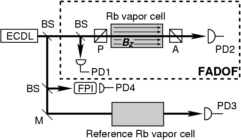
Generally speaking, a Faraday anomalous dispersion optical filter (FADOF) consists of an atomic vapor cell placed between two crossed polarizers. An homogenous, constant magnetic field of the strength B is applied parallel to the optical axis of the gas cell. Two effects govern the transmission of such a filter: the absorption of the atomic vapor and the polarization rotation of the incident light. The polarization rotation originates from the Zeeman splitting of the atomic transitions, which causes a difference in index of refraction for right and left circular polarized light. The latter effect is similar to the regular Faraday effect, but is much enhanced in the vicinity of absorption lines(1). The degree of rotation is strongly wavelength dependent and thus the crossed polarizers in combination with the gas cell act as sensitive transmission filters(2).
FADOF systems have been considered in the literature mostly as daylight suppression filters for use in communication(3). Since off resonant light is blocked by crossed polarizers FADOFs typically show passbands of a few GHz only and a high out-of-band suppression(3). Other advantages of FADOF systems include a large field of view and their relative insensitivity to vibrations. A possible disadvantage is the restriction to the vicinity of atomic transitions. However, FADOF systems of excited states have been implemented(4,5). These works are of particular interests as some of the alkali have excited state transitions within the range of frequency doubled Nd:YLF or Nd:YAG lasers.
In remote sensing applications such as our Opens internal link in current windowBrillouin project often small frequency shifts must be detected. An established method for this task is the use of edge filters5. The basic idea is to provide steep transmission edges of the filter in the regions of interest. Small shifts in the frequency of the signal will thus yield a large change in transmission. After calibration of the system, the determination of the frequency shift is therefore transfered to an intensity measurement.
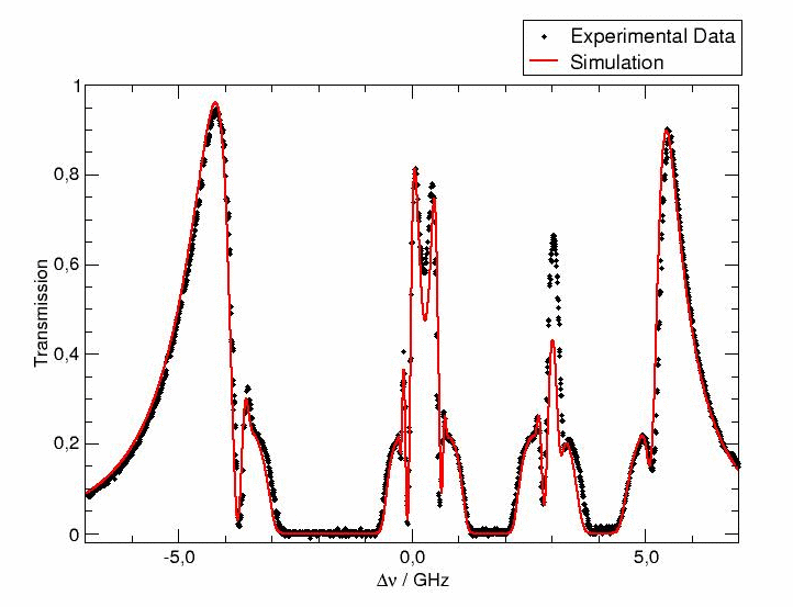
Currently we are evaluating the potential of FADOF systems as frequency analyzing tools for our Opens internal link in current windowBrillouin project. By setting the temperature of the gas cell and appropriately tuning the magnetic field FADOF systems are capable of producing steep transition edges at the desired frequency separation. The first step was to set up a FADOF experiment, work out the theory and compare the experiment with the theoretical prediction. The agreement between theory and experiment is excellent. Therefore, we are now working on implementing an excited state FADOF (ESFADOF) system in order to evaluate the FADOF's potential as an edge filter in the 532-nm wavelength range.
- D. Macaluso and O. Corbino, C.R. Acad. Sci. 127, 548 (1898).
- Y. Ohman, Stockholm Obs. Ann. 19, 3 (1956).
- D. Dick and T. Shay, Opt. Lett. 16, 867 (1991).
- T. Shay, in Proceedings of the IEEE Lasers and Electro-Optical Society's Annual Meeting (1993), pp. 359-360.
- R. Billmers, S. Gayen, M. Squicciarini, V. Contarino, W. Scharpf, and D. Alloca, Opt. Lett. 20, 106 (1995).
- C. Korb, B. Gentry, and C. Weng, Appl. Opt. 31, 4202 (1992).
Pulsed lasers have a minimum bandwidth which is limited by the Fourier transformation, i.e. given a certain pulse duration the band width of the corresponding pulse can never be smaller than this limit [1]. The Fourier transform limited bandwidth obviously depends on the exact pulse form, but as a rule of thumb one finds that 44 MHz is the bandwidth limit for a 10 ns pulse. The corresponding bandwidths for other pulse lengths can be computed easily based on this rule of thumb (for instance 44 GHz is the bandwidth limit for a 10 ps pulse).
Considering this natural bandwidth limit, it is particularly challenging to produce bandwidth limited laser pulses in the nano-second regime. Those pulses are generally generated by using a Q-switch, which acts as a fast off/on switch of the cavity. The cavity is switched “off” while the inversion in the laser is produced. Once it has built up, the cavity is switched “on” enabling feedback and thus amplification by stimulated emission. Usually, the radiation on a few longitudinal modes of the laser cavity is amplified and emitted leading to non-Forurier transform limited linewidths. A very common technique to achieve Fourier transform limited laser pulses in such a Q-switched alser is injection seeding.
The underlying idea of injection seeding is that one particular longitudinal mode of the slave laser is pre-populated with photons from a master laser. Once the laser action starts, this particular mode has a head start: Rather than from vacuum it starts pre-populated, thus gets more gain, grows more rapidly and finally takes over. More information including mathematical descriptions can be found in an extensive list of publications. As examples, we list the following references [2].
The requirement of this technique is that the slave cavity must be kept in resonance with the photons from the master laser. Several methods exist to achieve this condition.
This is one of the standard techniques for stabilization of a cavity. The cavity length is dithered across a resonance and is stabilized by monitoring the transmission of the cavity and generating an error signal, which is used as the feedback on a piezo mounted mirror. An example for a practical implementation of this system can be found in [3].
Most commercial Nd:YAG systems use this technique. If the pre-population of the cavity mode is optimum, the build-up time of the laser is minimized. The build-up time refers to the time it takes for the laser radiation to build up, i.e. the time from firing the Q-switch until the laser pulse actually exits the cavity. For the build-up time technique this time is constantly monitored and minimized on average. An obvious problem of this technique is that there is no way of measuring the direction of deviation from the optimum cavity length. Thus, the feedback occurs in a random fashion and can only be found rather slowly once a deviation has been detected. In practice one finds that the technique only works reliably for a pre-defined carefully optimized repetition rate of the laser system. In commercial systems, this is between 10 Hz and 100 Hz. Additional information can be taken from the literature [4].
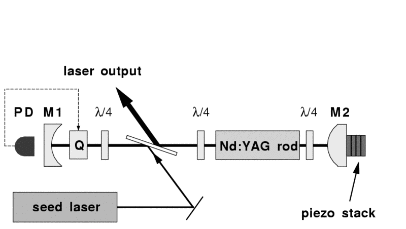
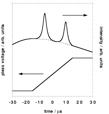
The set-up for this technique is depicted below. The light leakage through mirror M1 is monitored by means of a photo diode, while a piezo stack mounted on mirror M2 ramps the cavity length. The photo diode signal detects an interference signal from the interference of the seed light, which has made one round trip through the cavity and light that leaks out directly. When the interference shows a maximum, the seed laser is in resonance with the cavity and the Q-switch can be fired.
An obvious advantage of this technique is that once the firing of the laser occurs, the resonance is guaranteed. This system therefore works on a single-shot basis and under any environmental condition. A disadvantage is that the exact timing is uncertain, i.e. the laser could fire at any time during the voltage ramp and a synchronization with other events might be impossible. This technique was pioneered by E.S. Fry and co-workers [5].
The ramp-hold-fire technique is a closely related to the ramp-fire technique. After the ramp is fired and the resonance has been detected, the ramp is stopped and the length of the cavity is held constant until after a pre-defined time after the start of the ramp, the Q-switch is fired. Obvious advantages are that now the laser shot occurs at a fixed time and synchronizing different events becomes easy. A practical problem is that due to the need to hold the ramp, ramping times have to be reduced in order to avoid mechanical ringing in the system [6]
For completeness, we list the self-seeding technique, in which two resonators are coupled. One acts as the small linewidth master cavity and the second as the high-power slave oscillator. More information can be taken from the literature[7].
D.J. Bradley, Methods of generation, in: Ultrashort Light Pulses, Topics of Applied Physics 18, S.L. Shapiro (ed.), Springer Verlag (Heidelberg, 1977), chap. 2, p. 17-81
U. Ganiel, A. Hardy, and D. Traves, Analysis of Injection Locking in Pulsed Dye Laser Systems, IEEE J. of Quant. Elec. QE-12, p. 704 (1976); S. Basu and R.L. Byer, Short Pulse Injection Seeding of Q-Switched Nd:Glass Laser Oscillators – Theory and Experiment, IEEE J. of Quant. Elec. 26, p. 149 (1990); N.P. Barnes and J.C. Barnes, Injection Seeding I: Theory IEEE J. of Quant. Elec. 29, p. 2670 (1993); J.C. Barnes, N.P. Barnes, L.G. Wang, and W. Edwards, Injection Seeding II: Ti:Al2O3 Experiments, IEEE J. of Quant. Elec. 29, p. 2684 (1993)
A. Kasapi, G.Y. Yin, and M. Jain, Pulsed Ti:Sapphire laser seeded off the gain peak, Appl. Opt. 35 p.1999-2004 (1996)
R.L. Schmitt and R.A. Rahn, Diode-laser-pumped Nd:YAG laser injection seeding system, Appl. Opt. 25 pp. 629-633 (1986)
S. Henderson, E.H. Yuen, and E.S. Fry, Opt. Lett. 11, p. 715 (1986); E.S. Fry, Q. Hu, X. Li, Single frequency operation of an injection-seeded Nd-YAG laser in high noise and vibration environments, Appl. Opt. 30 p.1015-1017 (1991).
Th. Walther, M. P. Larsen, and E.S. Fry, Generation of Fourier-transform-limited 35-ns pulses with a ramp-hold-fire seeding technique in a Ti:sapphire laser, Appl. Opt.-LP 40, pp. 3046-3050 (2000)
N.P. Barnes, J.A. Williams, J.C. Barnes, and G.E. Lockard, A self injection locked, Q-switched, Line-Narrowed Ti:Al2O3 laser, IEEE J. of Quant. Elec. 24, p. 1021 (1988) ; D-K. Ko, G. Lim, S.H. Kim, B-H Cha, and J. Lee, Self-seeding in a dual-cavity type pulsed Ti:sapphire laser oscillator, Opt. Lett. 20 p. 710 (1995)
Let's assume we have a laser beam at a given wavelength impinging on a non-linear crystal. If conditions are properly chosen (see below), we observe not only the original laser beam after the non-linear crystal, but a second laser beam having a different color. Closer inspection yields that the additional beam has exactly twice the frequency or half the wavelength of the original laser beam. Therefore, we talk about the second harmonic of the first one. But how does this come about?
Usually an applied electric field will produce a polarization in a material which is proportional to the electric field itself. If, however, the electric field gets larger – fields of the required magnitude can easily be generated by lasers, it can produce a contribution to the polarization which is proportional to the square of the electric field. Thus, the polarization reacts in a non-linear way to the electric field. The polarization in turn then produces electric field components at additional frequencies. The effect is comparable to a stereo system with the volume turned up. At some point the amplifiers will react in a non-linear fashion and additional frequencies occur as a result: the sound is distorted.
Assuming that laser radiation made up of two different frequencies is impinging on the crystal, one can show by use of the trigonometric addition theorems that due to the non-linear interaction different cases may occur as a result on the non-linear interaction: second harmonic generation of either frequency, sum frequency generation (SFG), difference frequency generation (DFG) and optical rectification (OR). The exact process depends on (1) the type of non-linear crystal (2) the geometry at which the crystal is cut (3) polarization of the input beams
Two other conditions govern the process: (1) conservation of energy and (2) conservation of momentum which is sometimes called phase matching.
Conservation of energy can be understood in a particle picture quite easily. Two photons at the fundamental frequency are annihilated and one at the second harmonic is created. Thus, the overall energy of the process is conserved.
In the particle picture of SHG, momentum conservation demands that the two momenta of the annihilated photons add up to the momentum of the created photon at the second harmonic. In the wave picture momentum conservation is referred to as the phase matching condition. The phases of the second harmonic wave must be in phase throughout the crystal such that the different parts interfere constructively at the end of the crystal and a macroscopic wave at the second harmonic emerges form the crystal. In a collinear, type-I configuration (i.e. when the fundamental and second harmonic propagates collinearly through the crystal) the phase matching condition is identical to the condition that the indices of refraction of the fundamental and second harmonic wave are identical, which means that the phase velocities of the beams are identical.
Phase matching is only possible in birefringent materials, i.e. materials whose index of refraction depends on the polarization and direction of propagation of light. One distinguishes two types of phase matching: type-I and type-II, respectively. In type-I processes the two photons at the fundamental frequency have the same polarization, in a type-II process the two photons have orthogonal polarization.
The efficiency of SHG scales quadratically with the intensity the input beams and assuming interaction of Gaussian beams linearly with the length of the non-linear crystal. A potential problem is the so called walk-off between the different interacting beams. Walk-off is a feature of birefringent crystals and referrs to the fact that in general for the so-called extra-ordinary ray phase front and direction of energy transport are tilted with respect to each other.
- R.W. Boyd, Non-linear Optics, Academic Press, (1992, San Diego)
- Y.R. Shen, The Principles of Nonlinear Optics, Wiley, (1984, New York)
- A. Ashkin, G.D. Boyd, J.M. Dziedzic, Resonant optical second harmonic generation and mixing, IEEE J. QE 2 (1966), p. 109-124
- G.D. Boyd and D.A. Kleinman, Parametric interaction of focussed Gaussian light beams, J. Appl. Phys. 39 (1968) pp. 3597-3637
- R.L. Byer, Parametric Oscillators and non-linear Materials in Nonlinear Optics – Proceedings of the 16th Scottish Universities Summer School in Physics, 1975,
- P.G. Harper and B.S. Wherrett (eds), Academic Press (1977, New York), pp. 47-160
- SNLO – software written by A. Smith to calculate many aspects of SHG and more
The radiation emitted by lasers has some very specific properties:
- coherent and monochromatic
- directed
- intensive
This means that the laser is excellent for many applications. You could almost say “it's one for all”.
Each of the properties mentioned above allow certain, very specific applications. Of course, the good focusability of a laser beam also makes it possible to manipulate the laser beam in such a way that it can be propagated over large distances. This enables applications in distance measurement, but also in environmental sensor technology, which is also being pursued in our group. However, in connection with modern, very low-absorption optical fibers, light can also be transported over very long distances and information can thus be transmitted. Communication on the internet is based on such fast laser data transmissions.
The high intensity in connection with the good focusability enables applications in production technology (drilling, cutting, welding) but also in medicine, e.g. eye operations, dentistry etc. Work is currently being carried out on laser procedures for surgical interventions that can significantly accelerate wound healing. Another application here is the acceleration of charged particles and research into laser-induced fusion, which may one day solve the energy problem.
The good focusability also has important applications in other intensity ranges, e.g. in connection with storage. The introduction of the Blueray Disc, simply by using a blue laser diode (instead of a red one) due to its better focusability, led to a four times higher storage density of the Blueray Disc compared to a standard DVD.
The coherence is related to the monochromaticity of the laser radiation. Monochromatic means that the laser emits a very well-defined color of light. It has no white color, but the emission shows a very specific, well-defined color. It is also said that the laser has a very narrow bandwidth.
On the one hand, this enables a very high selectivity for certain atoms or molecules, which makes the laser ideal for use in spectroscopy. This makes highly sensitive detection methods for trace gases etc. possible.
On the other hand, the high degree of coherence also makes it possible to use the laser as a high-precision measuring instrument. In this way, the constancy of the natural constants can be checked or the development of new, even more precise clocks becomes possible.